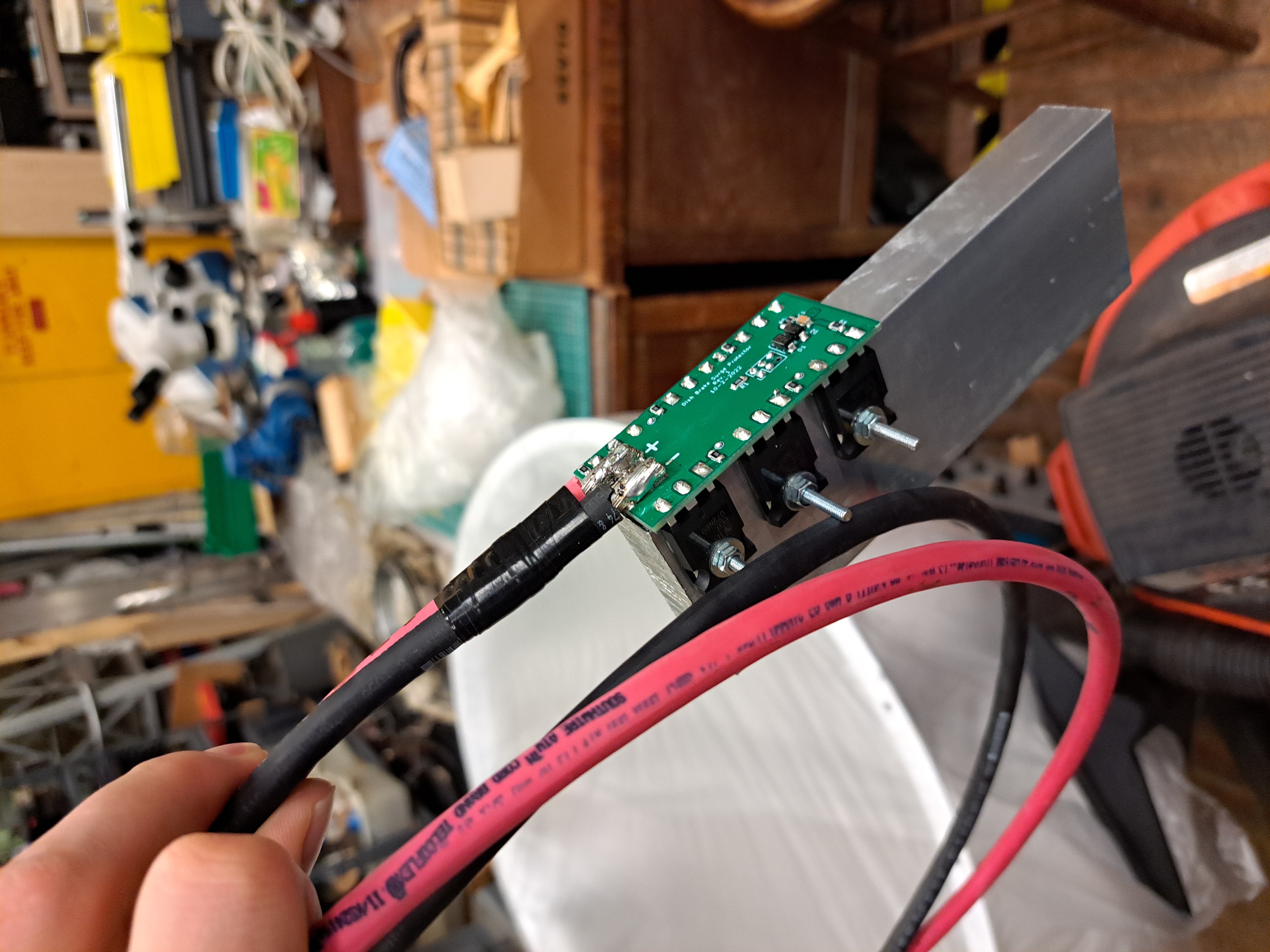
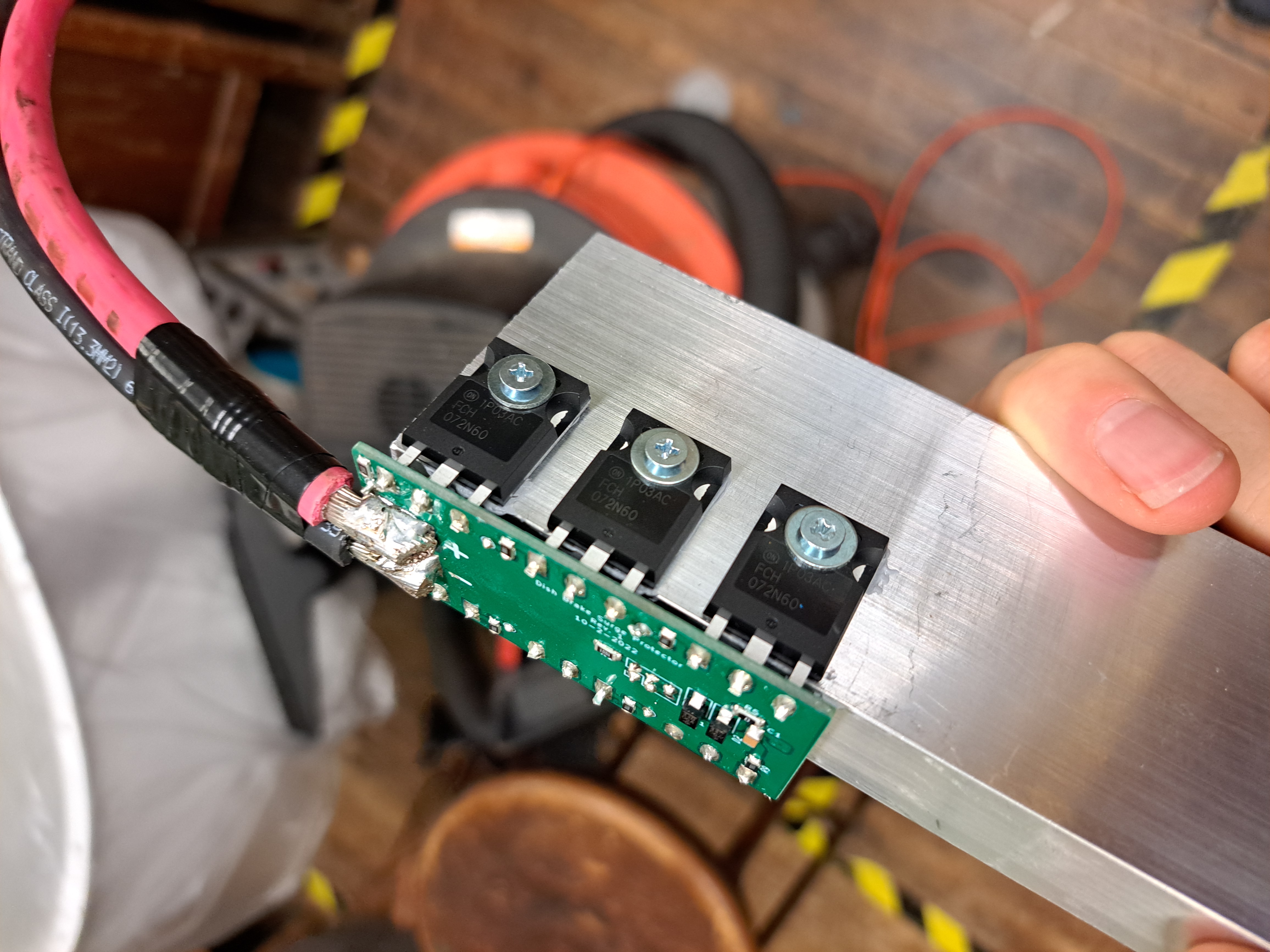
This is a shunt/crowbar circuit I made for the XM dish drive. This is designed to dissipate the kinetic energy in the dish if the drivers lose their grid connection and cannot brake. Six large FETs clamp the line voltage to about 60V if the line ever goes above 48V. The aluminum bar is sized to absorb the dish energy (2.5kW) without the FETs overheating. No heatsinking is necessary because this is only designed to take one pulse in a very unlikely emergency.
|
|
|
The circuit worked exactly as designed with a current limited bench supply, but we ran into trouble attempting to test it at full power. We were able to find a couple 50V 50A power supplies and wired them up to the three phase drop in the Radio Society shop, and set up a circuit that would quickly connect the second supply in series with the first with a knife switch to try to simulate a transient.
In reality, this was dangerous and finickly. I melted a $500 scope probe with the resulting arc, and the few times we did try it, we blew up something on the shunt board. We strongly suspected that this was an issue with inductance, which wouldn't be a problem on the real system which has a large amount of bus capacitance and the inertia of the dish to slow down the rise time. That said, we didn't have a way to slow down the rise time in our test fixture.
In the end, we bought a similar system from a commercial vendor that we could trust to do the testing for us. That device cost several hundred dollars, and were not allowed to run it through our test fixture before it was installed...