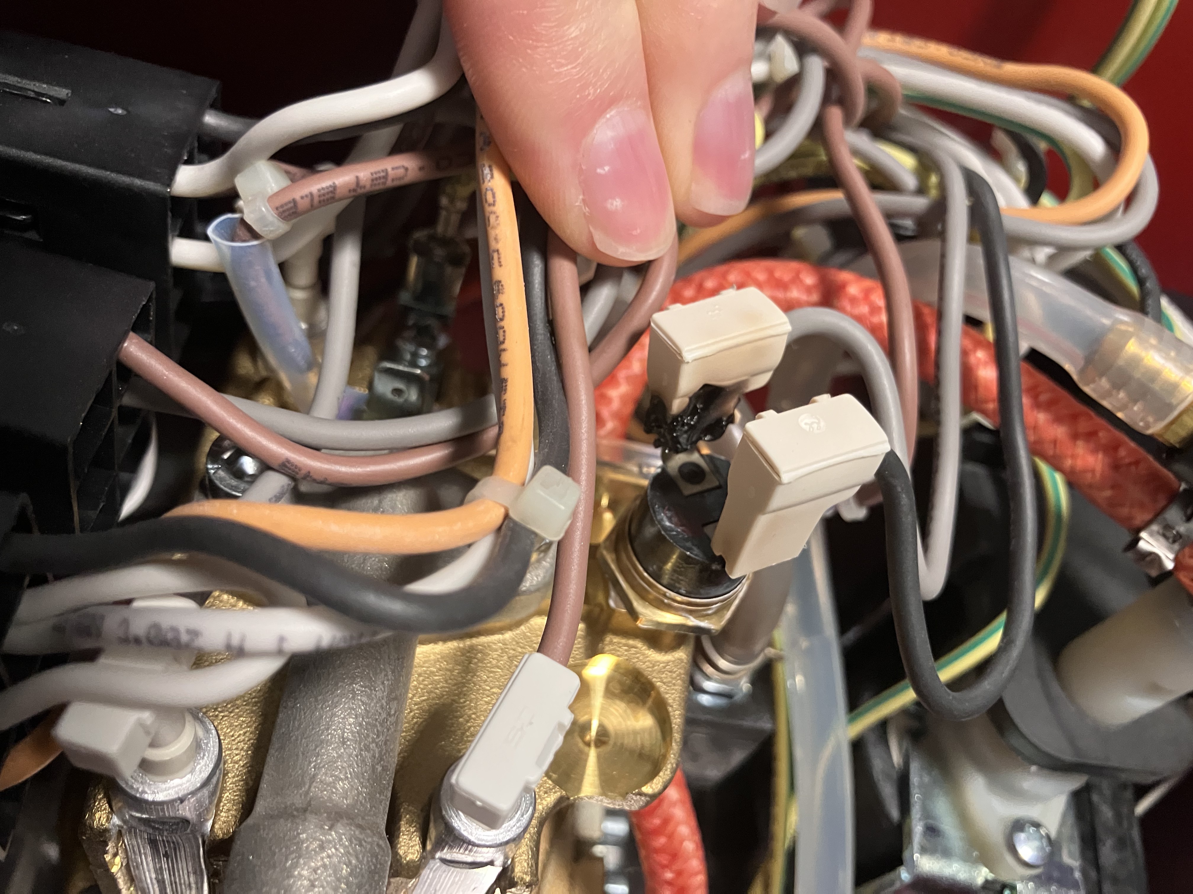
We have had a Gaggia Classic Pro espresso machine for about a year, and I am very fond of its minimalist controls and general simplicity. Unfortunately, after about six months of use, we started to notice a bad smell, and a few years later, it stopped heating altogether. Pulling open the cover, we discovered that the steam thermostat had melted/burned.
This prompted some reflection about the internal construction of the machine, and a lot of reading about other issues people have had with this machine. In particular, the boiler has been subject to a lot of scruitiny online after the original coated aluminum boilers started shedding flakes of nonstick coating into people's espresso. The newer machines (including ours) now ship with uncoated "lead-free brass" boiler, which some reddit users suspect are not in fact lead-free. Since I had the machine apart anyway, I decided to open up the boiler and take a look, and I was greeted by a whole lot of corroded slime.
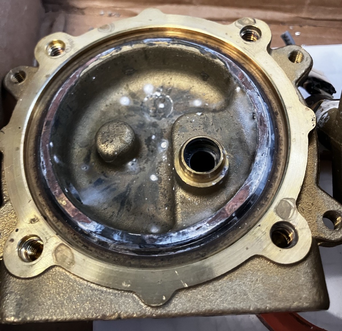
Setting aside the whole lead contamination controversy, the amount of corrosion inside the relatively small volume of the boiler was more than enough to ruin my love of espresso. Ultimately, I decided that I wanted a new boiler made of stainless steel.
The geometry of the group head is fairly complicated, since it provides the connections to the solenoid, pump, and portafilter/water distribution plate and screen. I suspect that the size of the channels for the water are important to the performance of the machine, so I decided that for the stainless steel version I would keep as much of the original geometry as possible.
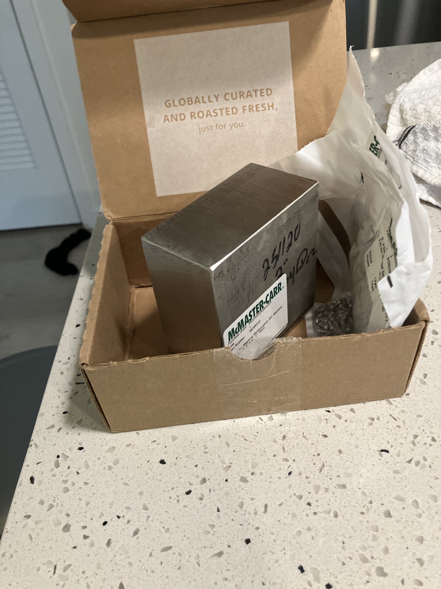
The group head is made from a 4x4x2.5" block of 306 stainless steel from McMaster-Carr.
|
|
|
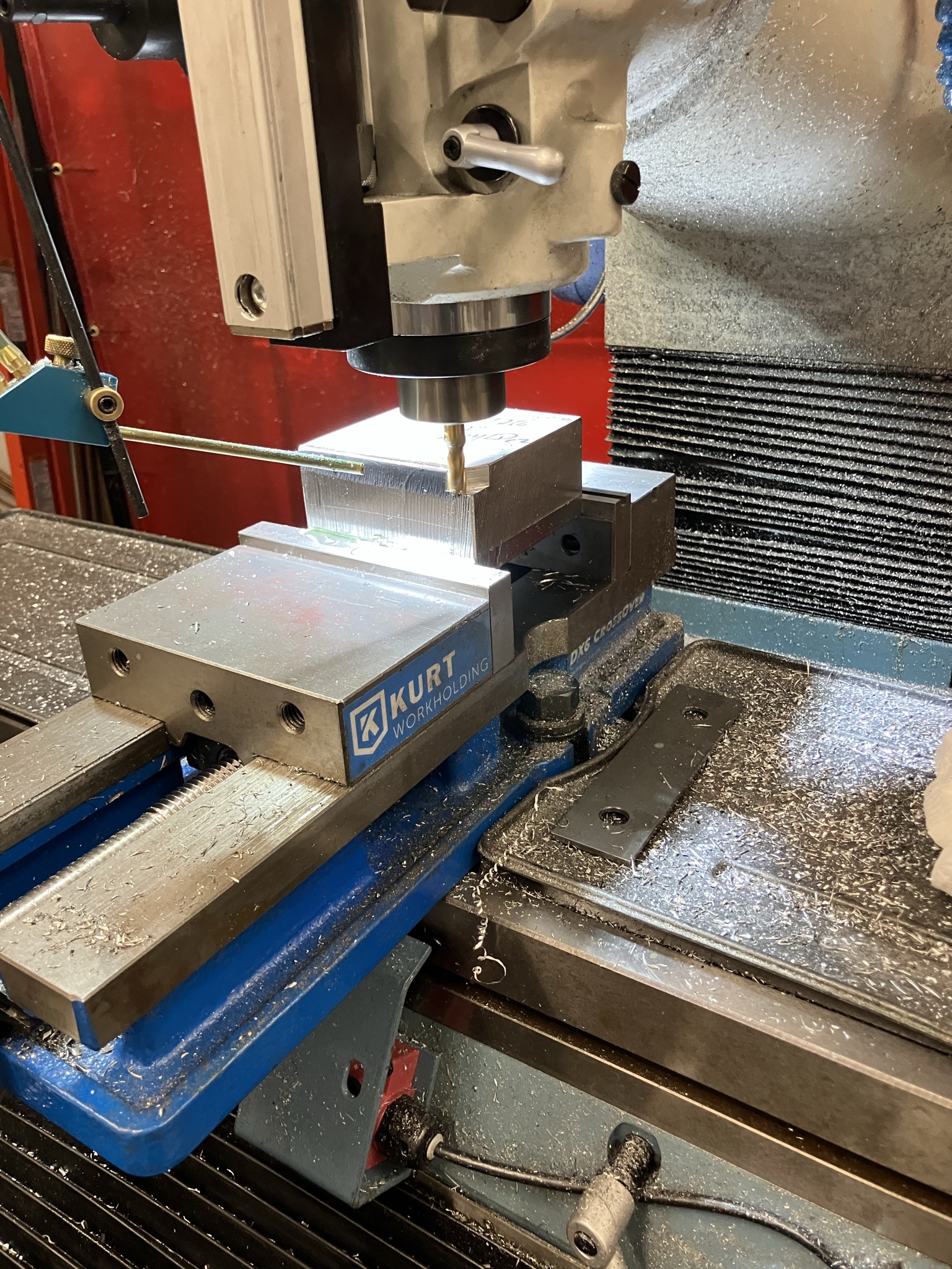
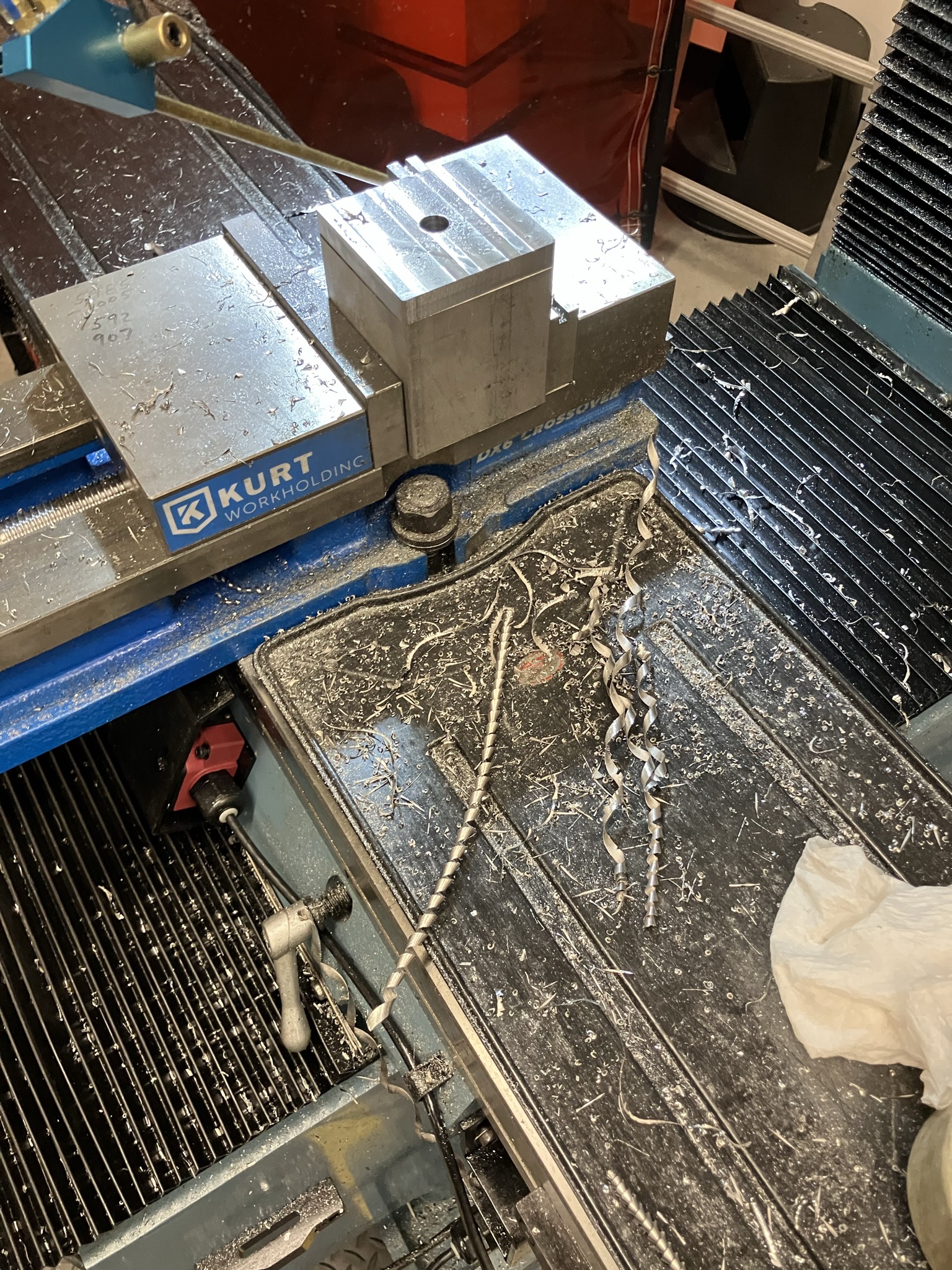
Since the original boiler is cast, there are a lot of features that are pretty inconvenient for machining, like a half-inch tall protrusion that holds the little pipe that pulls water down to the portafilter. This adds an extra half-inch to the stock that is nearly all removed in the first operation. This is followed by a contouring operation to get the outside profile and a pocket that forms the bottom of the boiler.
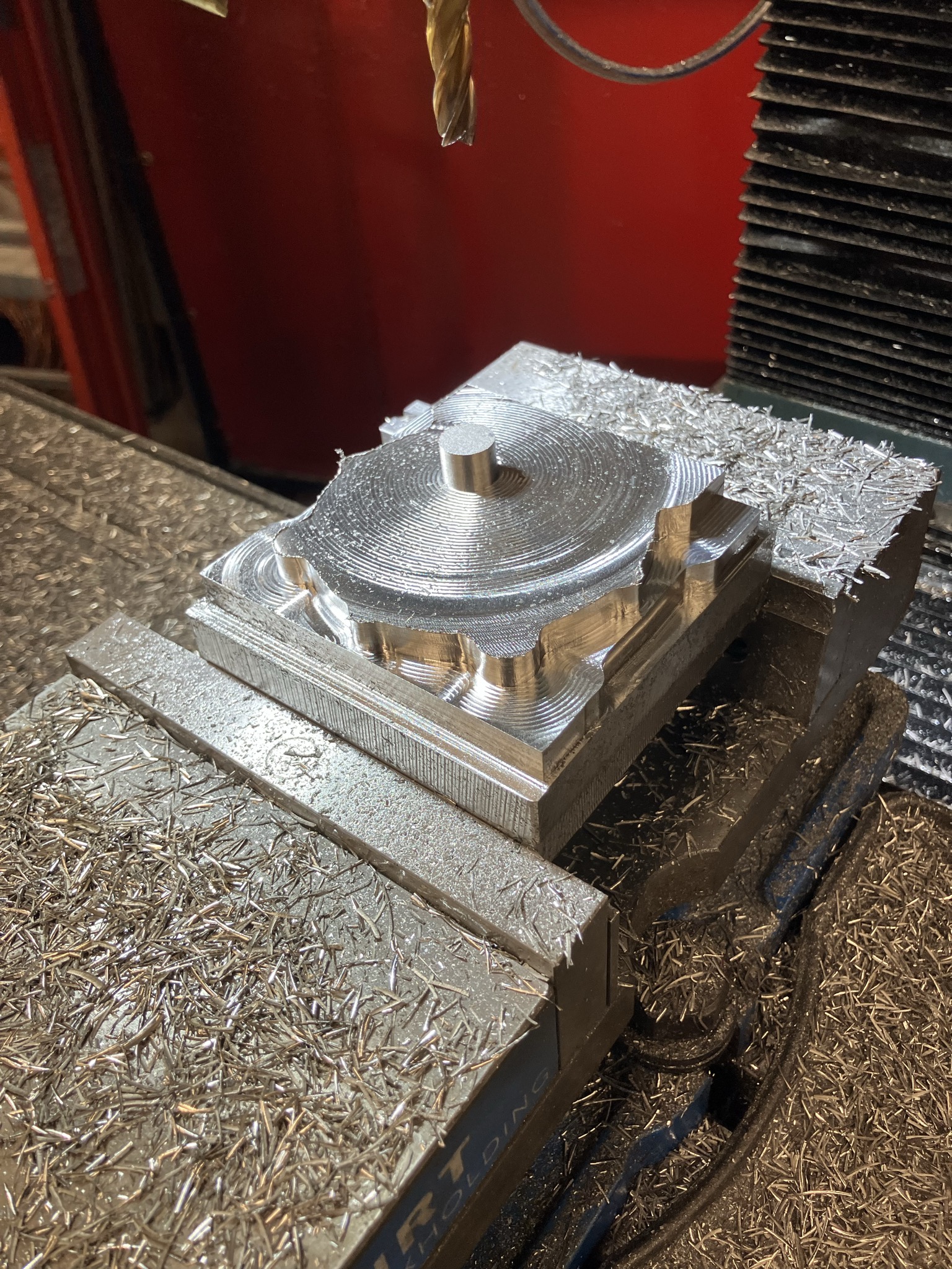
|
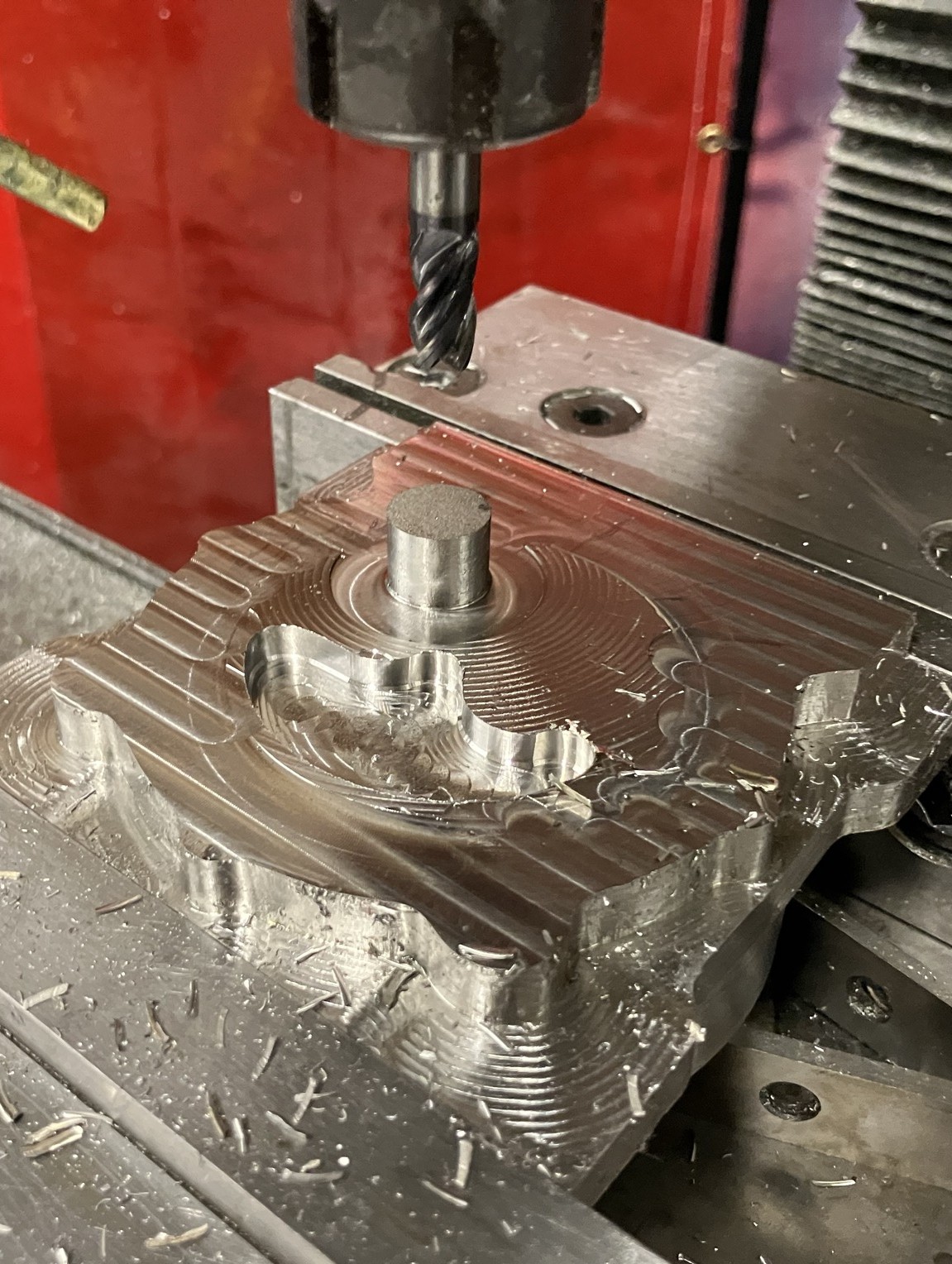
|
The bottom of the group head is also formed from a number of pockets and contours, but gets interesting when I need to cut the helical relief that engages with the portafilter. This is done with a t-slot mill. Finally, I got this dialed in on the four-jaw in the lathe to clean up the cyllindrical faces and chamfer the outside corner.
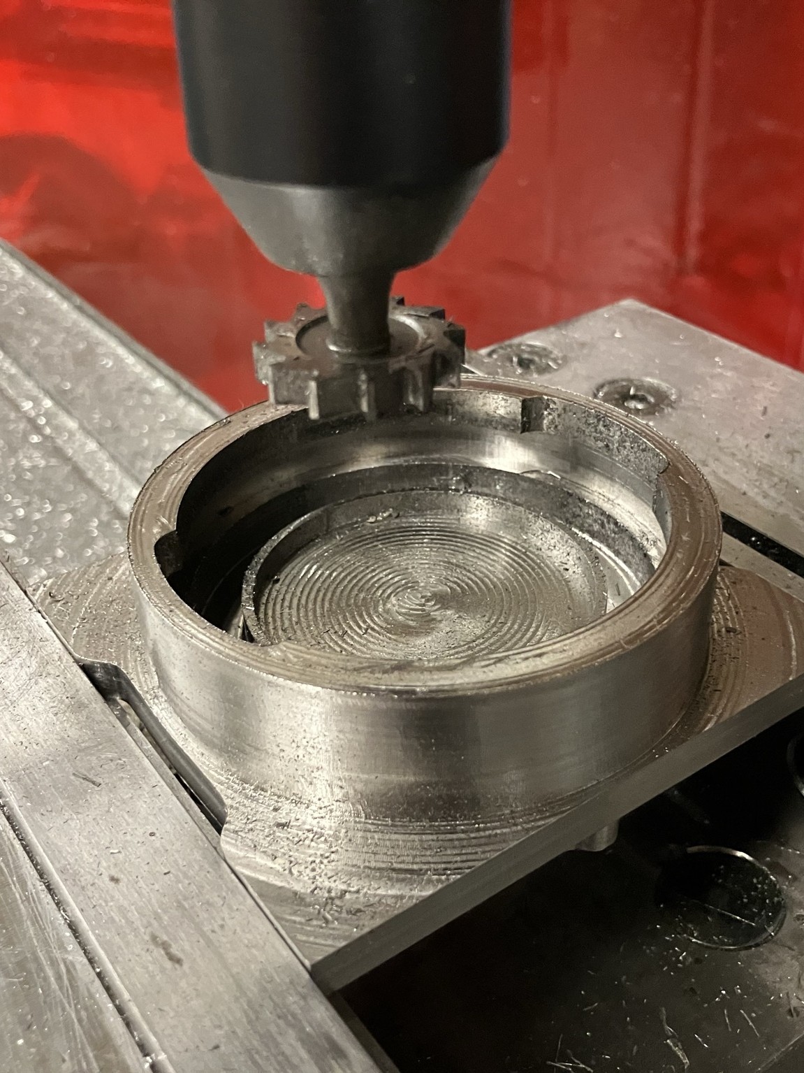
|
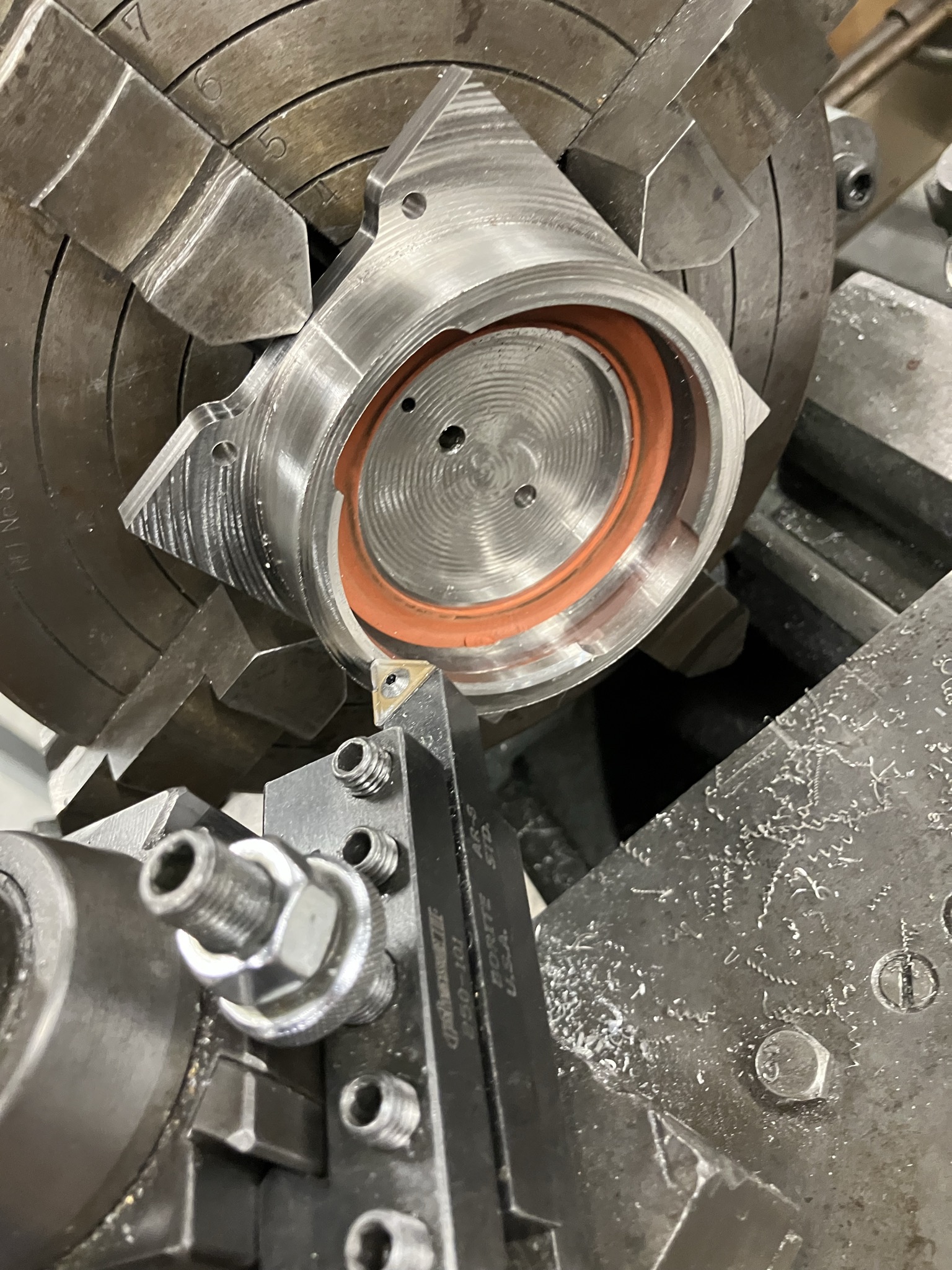
|
The group head gets a number of tapped and straight holes and then it was time to move on to the boiler.
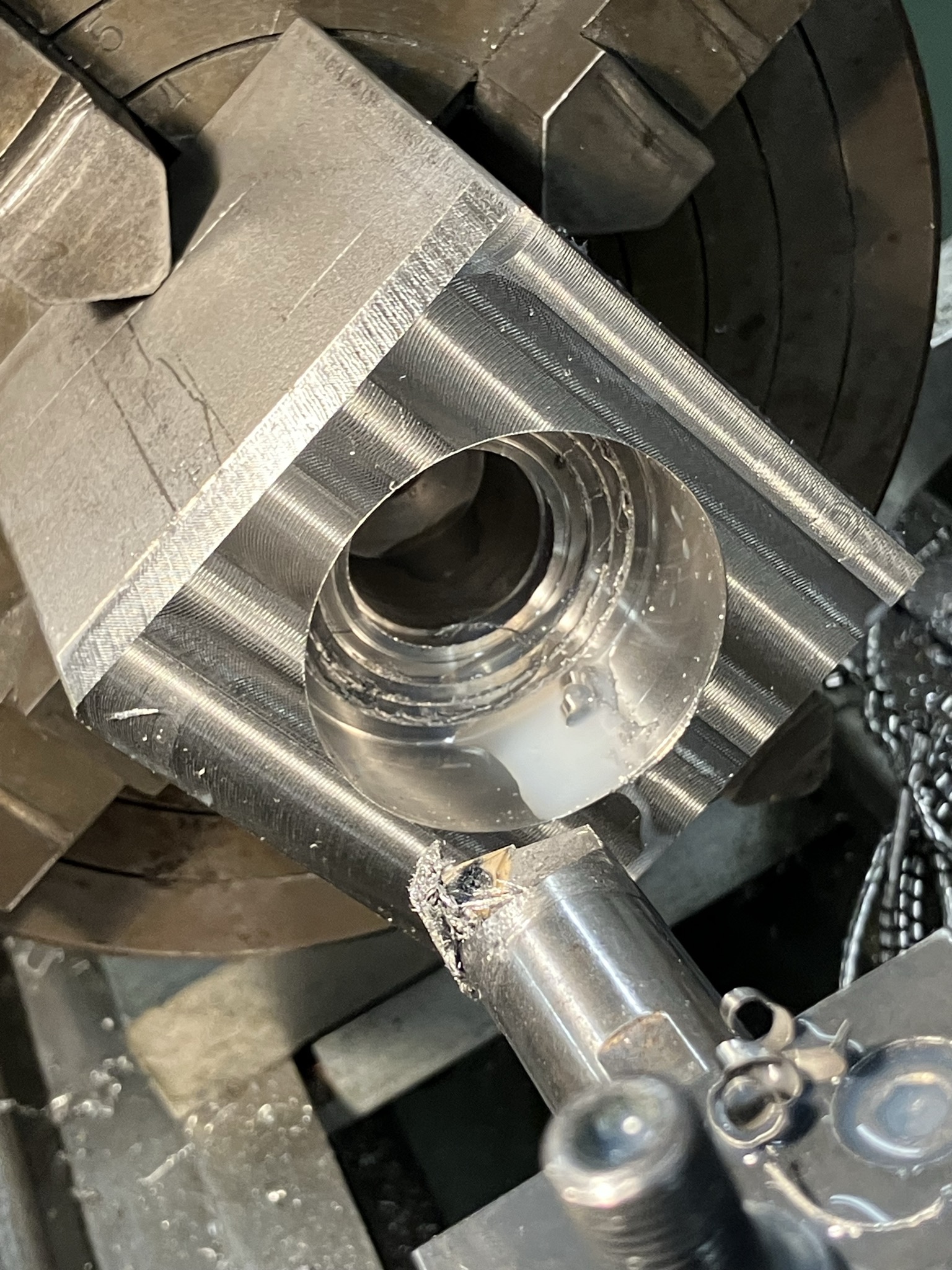
Since the group head took far longer than I anticipated, I decided to make some changes to the design of the boiler to simplify the machining. I started with another 3x3x4.5 inch block of 306 stainless. I started by drilling and then boring out the inside to form the chamber.
|
|
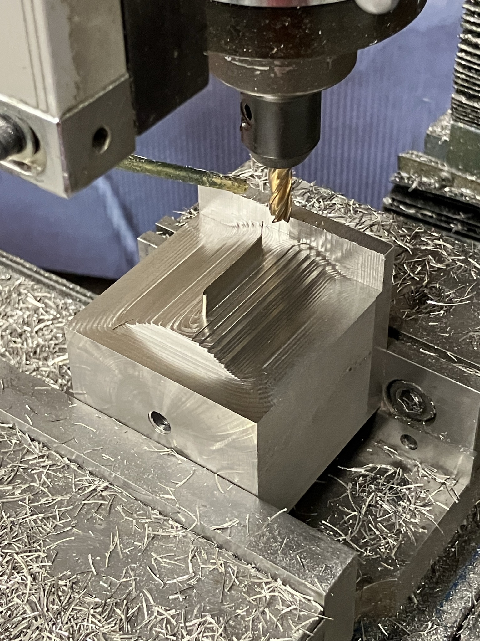
Next, I roughed the outside of the boiler with the part mounted sideways. This orientation afforded the highest material removal rate I could acheive, using a 5/16" TiN coated HSS endmill that really pulled its weight in this project (outliving two carbide endmills and the much larger diameter endmill used later).
|
|
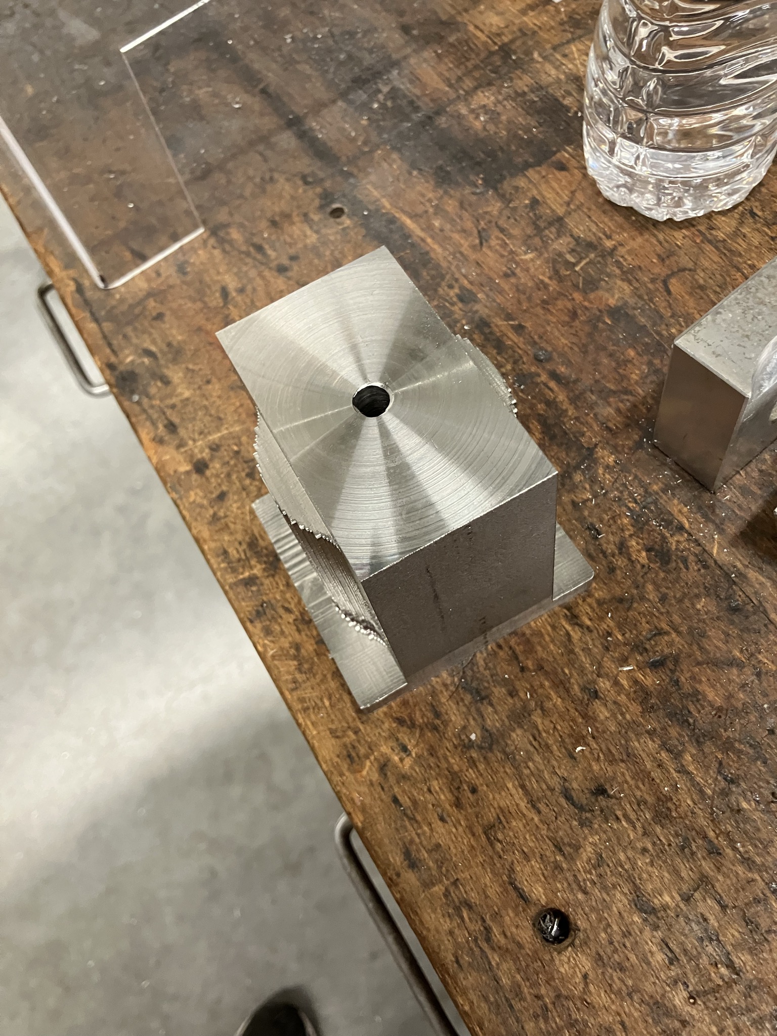
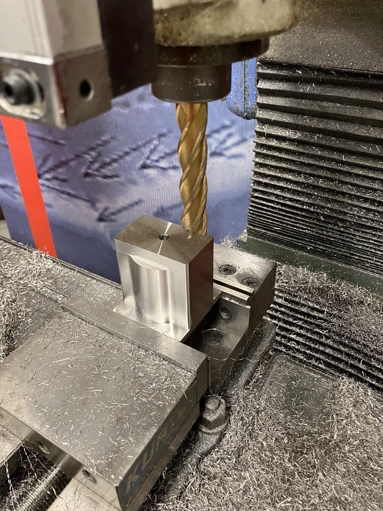
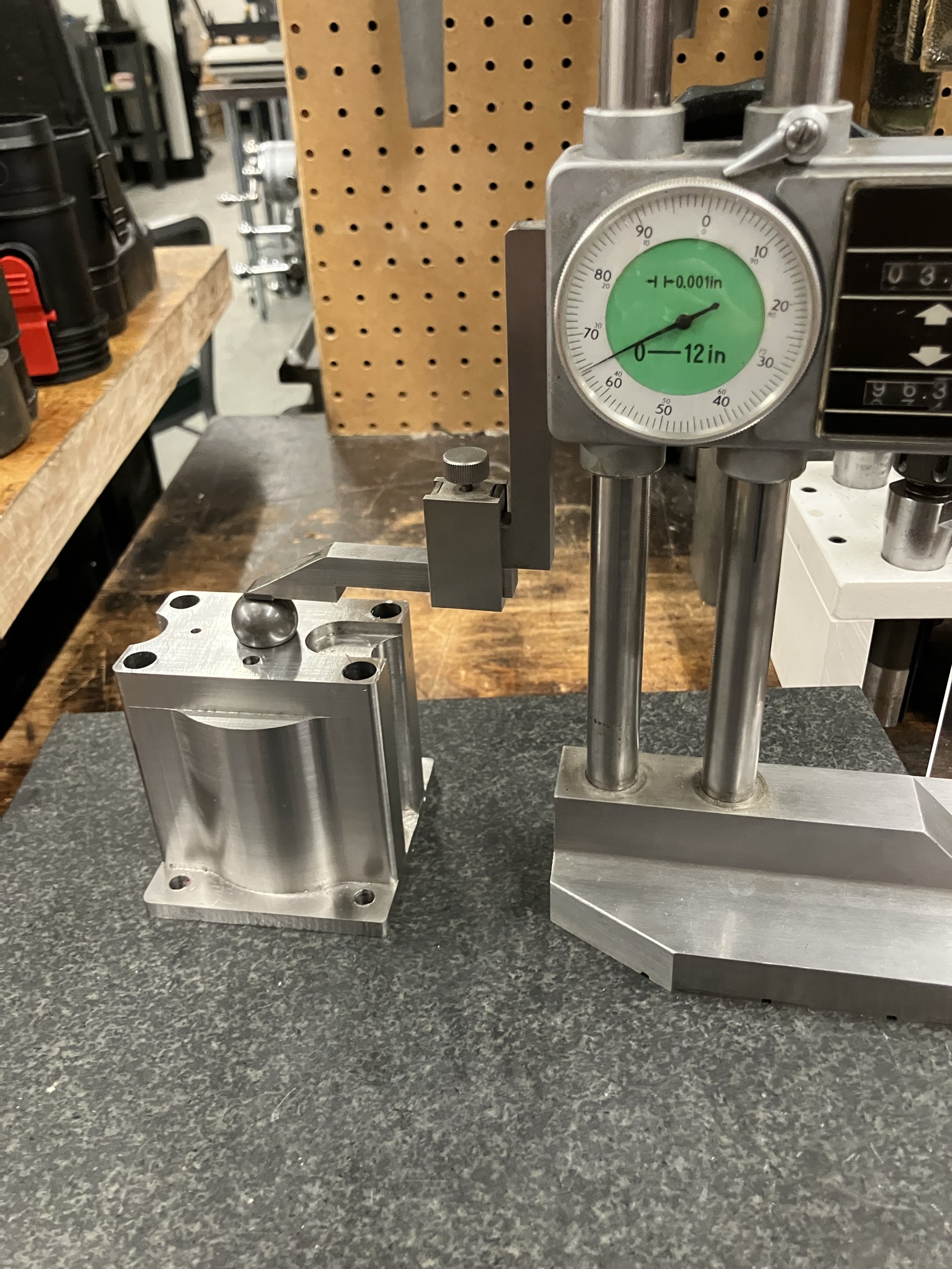
To finish the outside, I used a 3/4" diameter, 3" flute length endmill. Despite the large diameter, the tool length meant that I could only remove 4 thou per pass. After that, the boiler is finished by drilling several mounting holes and adding some reliefs to the sides by slowly plunging the 3/4" endmill in 20 thou steps. The top includes a particularly tricky chamfered O-Ring groove, which we measured using a height gauge and a surface plate.
|
|
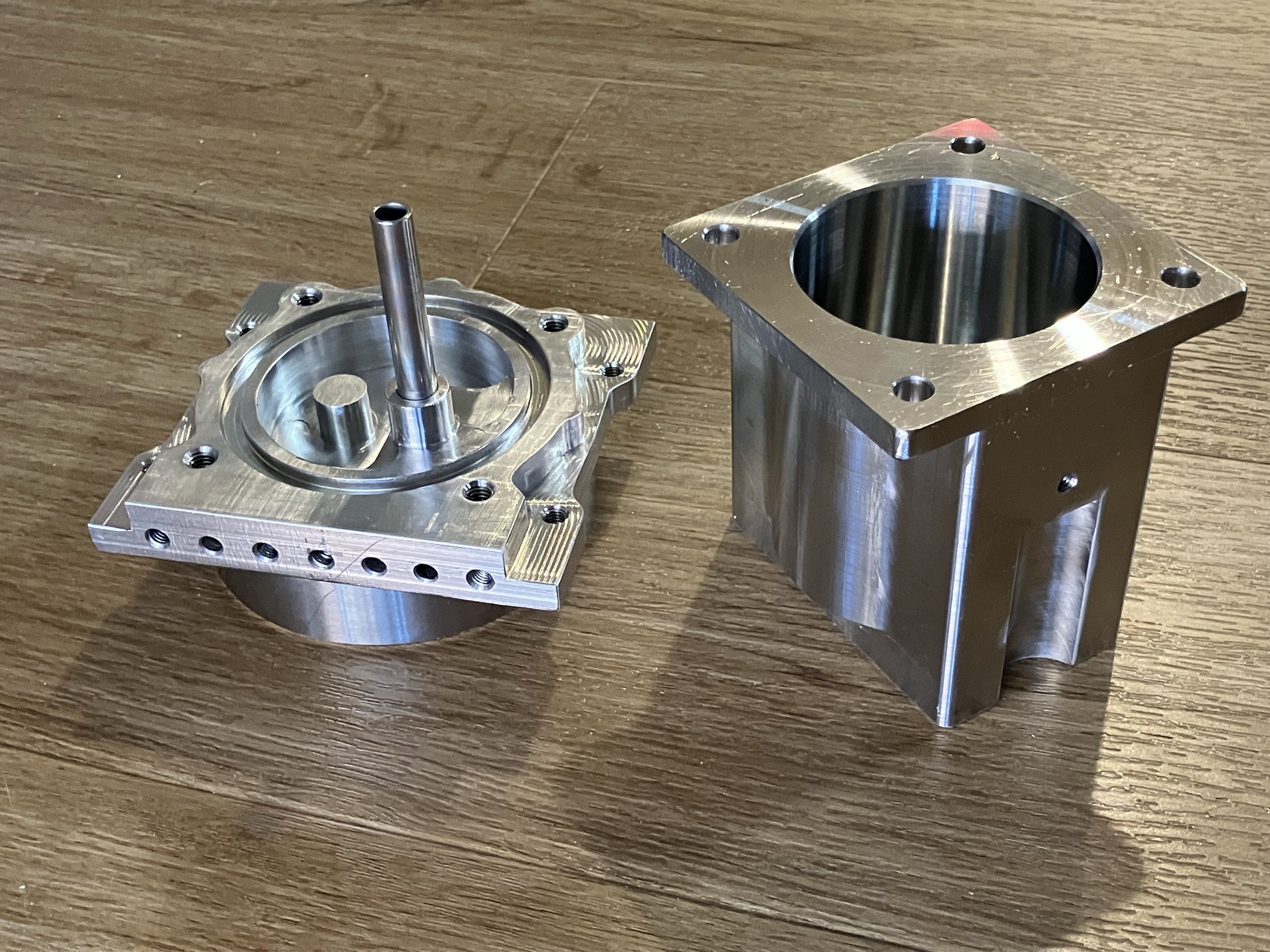
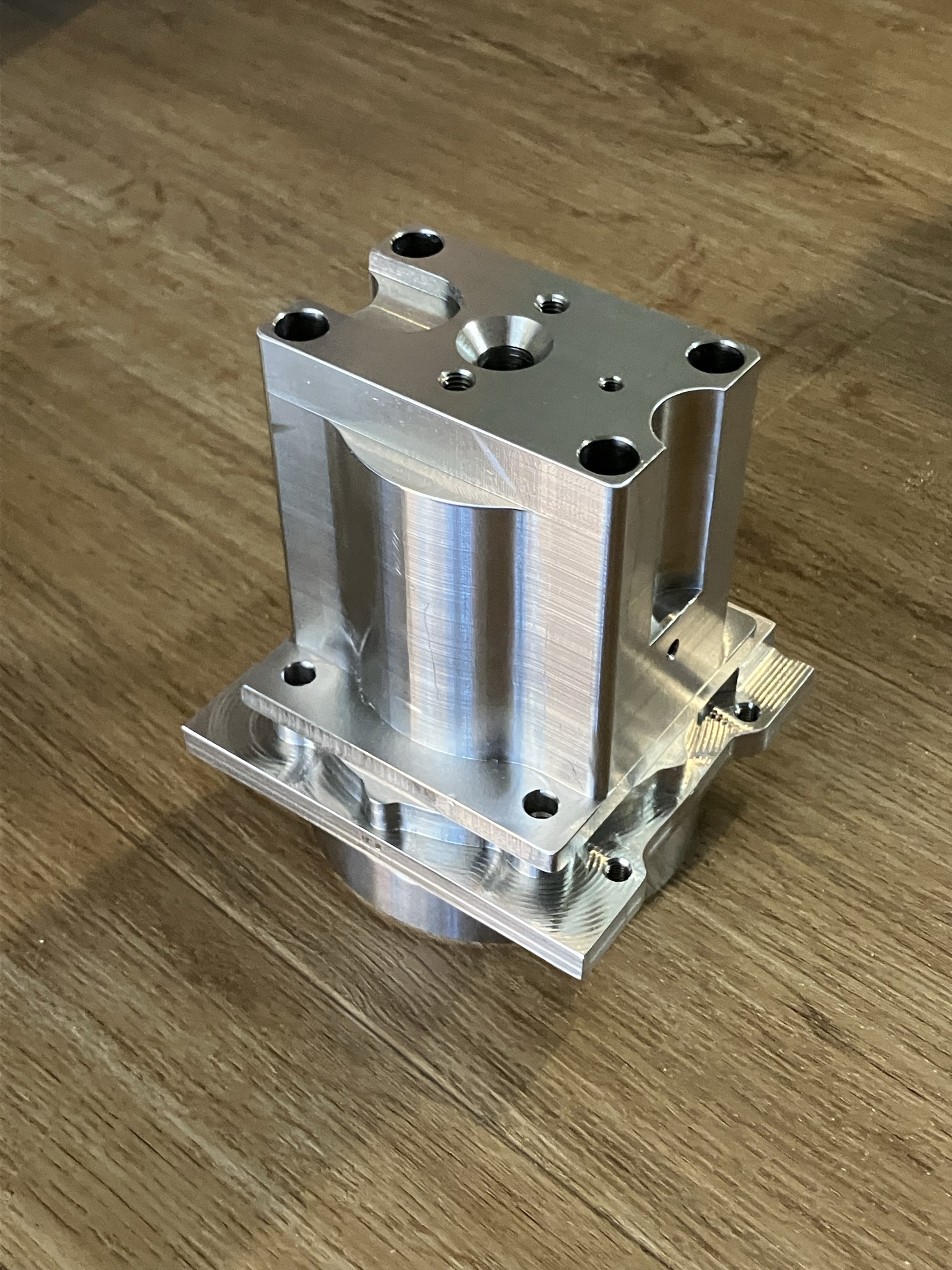
After an afternoon going over them with emory cloth, the boiler components were ready to go. I spent a long time cleaning them to get all of the oil and dirt off before they were ready for installation.
|
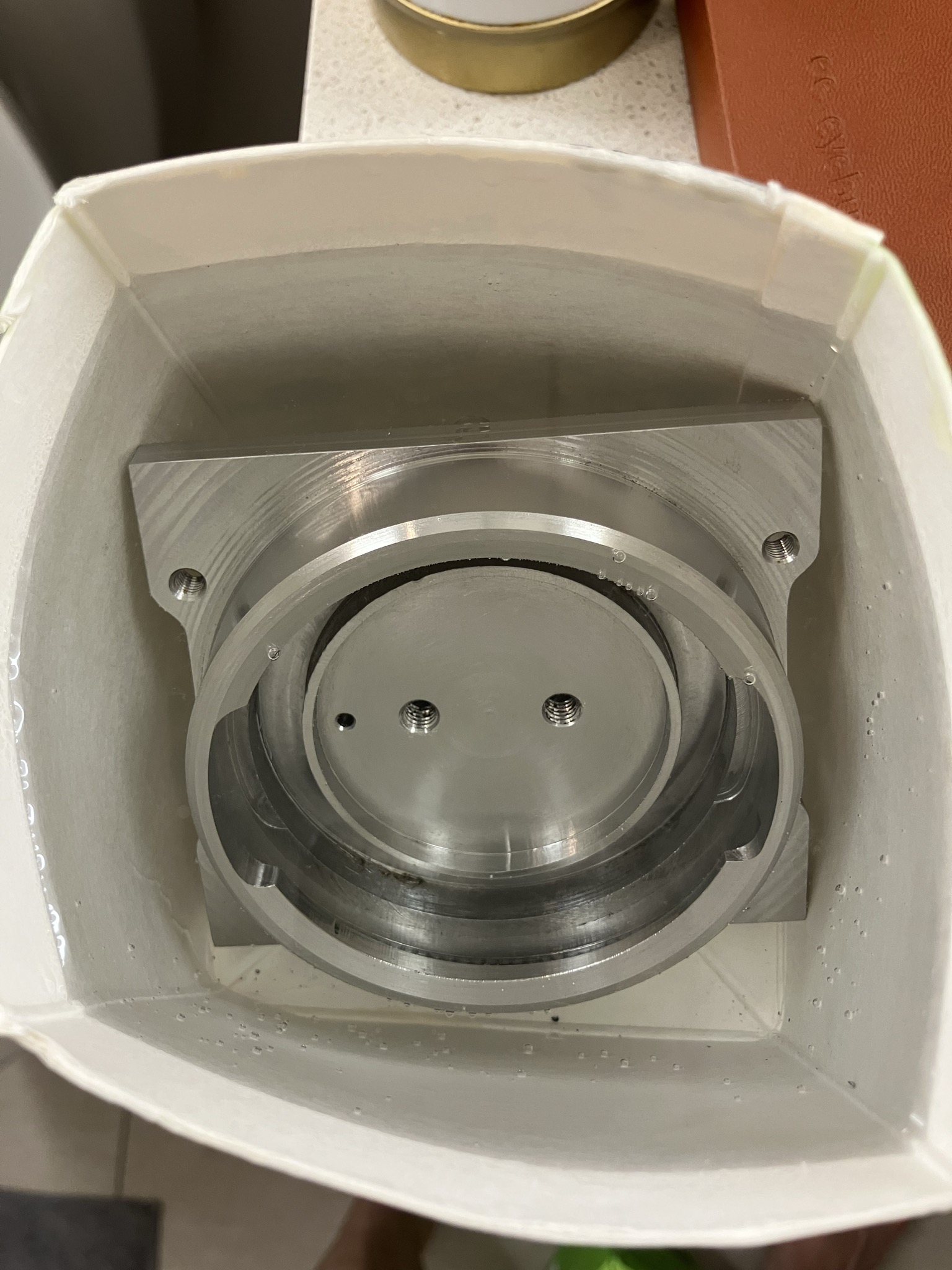
|
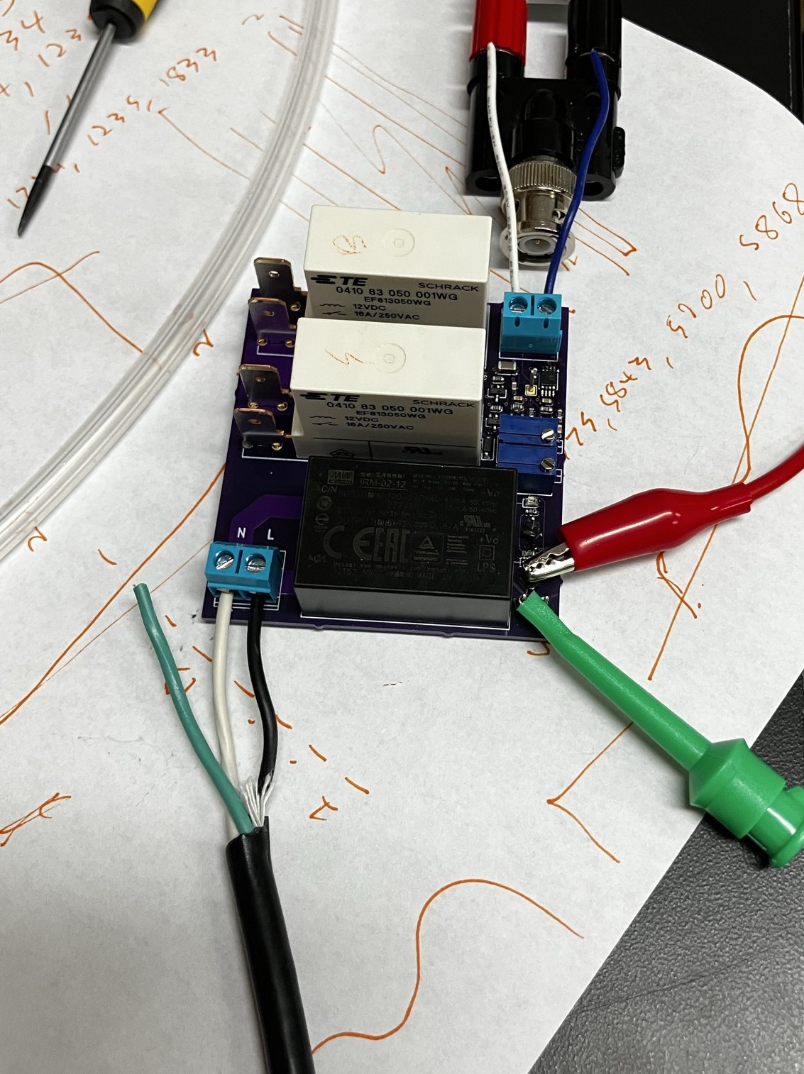
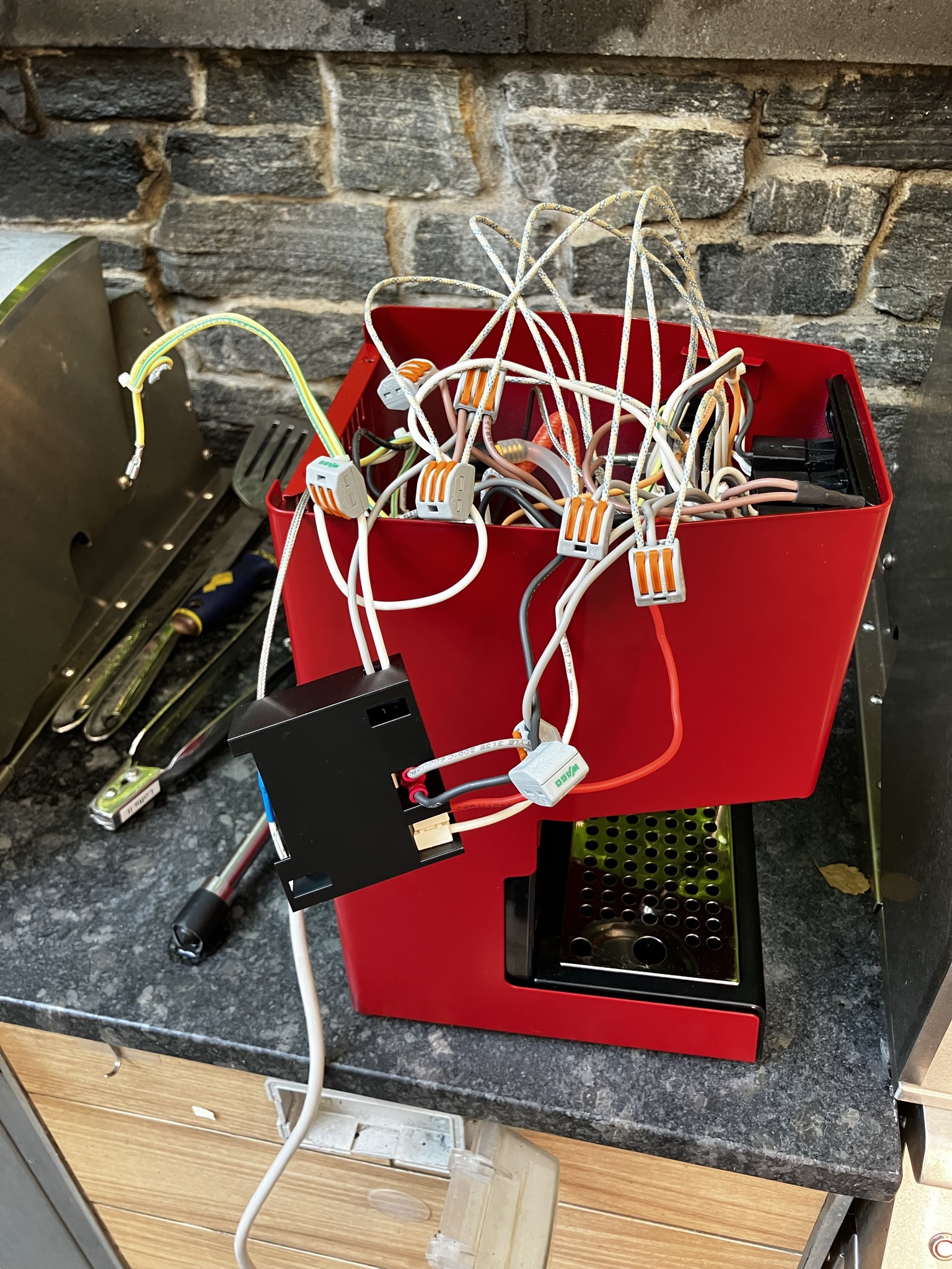
At this point, several months after starting this project, I had still done nothing to address the actual problem of the burned out steam thermostat. Looking online, several other people have reported exactly the same problem, always with the steam thermostat. While the current online consensus is that this has something to do with loose connections, I suspect that this is wrong, since it never seems to happen anywhere else. Instead, I suspect that it is unwise to attempt to switch upwards of 10 amps through a bimetallic thermostat operating at near it's operating temperature limit and that the failures are caused by thermal runaway on the contacts in the thermostat. The solution to this is to move the switching hardware away from the boilers, so that I can use proper industrial relays which never get much hotter than room temperature. I designed a little board with those relays and a thermocouple amplifier that is designed to exactly replicate the functionality of the two thermostats in the original circuit.
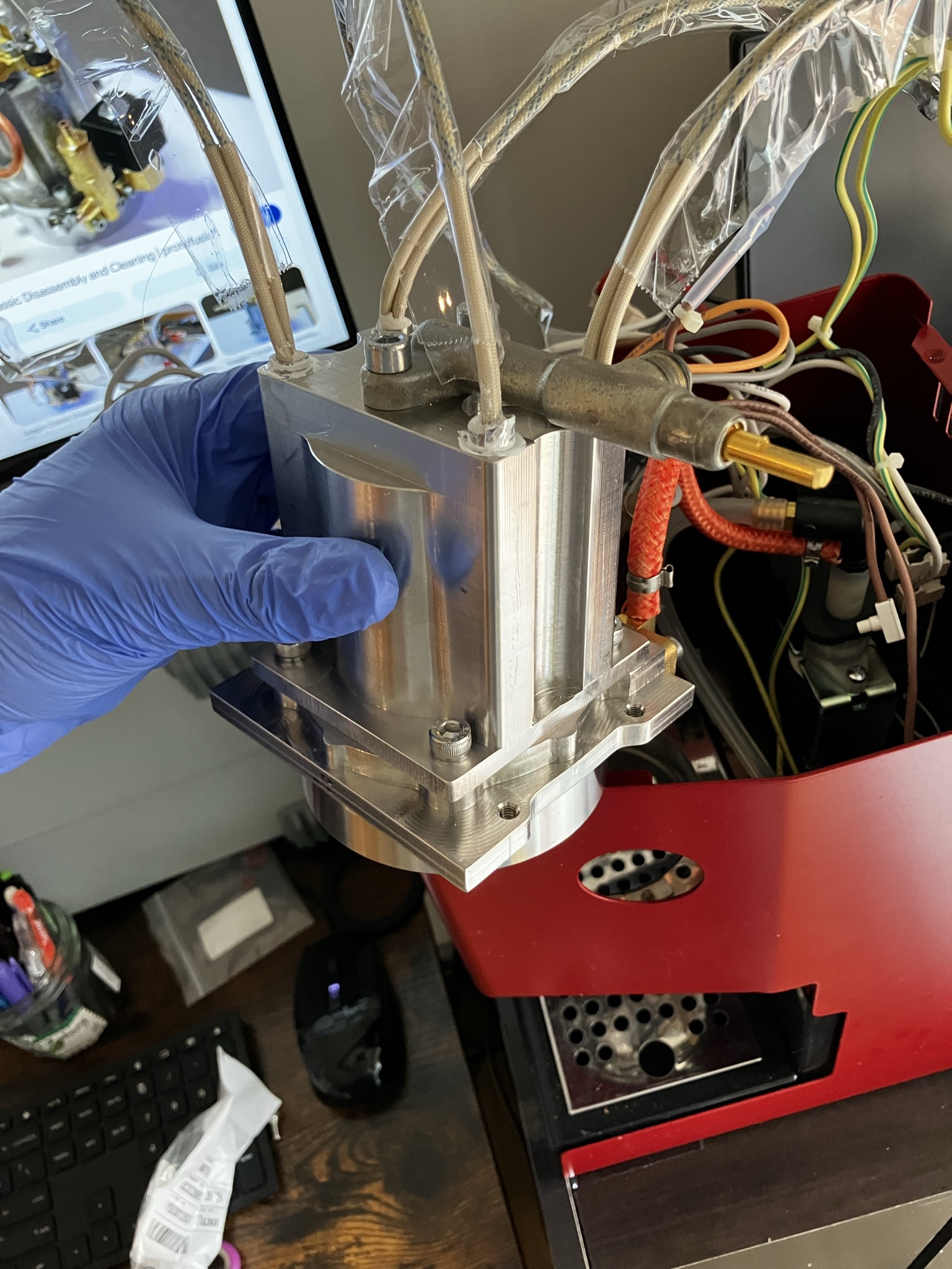
After a few weeks of false starts, I managed to buy all the parts I needed to put it all back together (in the five months it took to get this far, many of the smaller screws and O-rings vanished). The group head gets bolted to the pump inlet and solenoid, and then the filter holder gasket, shower holding plate and shower screen are bolted to the bottom. The top gets another O-Ring which seals the group head to the boiler.
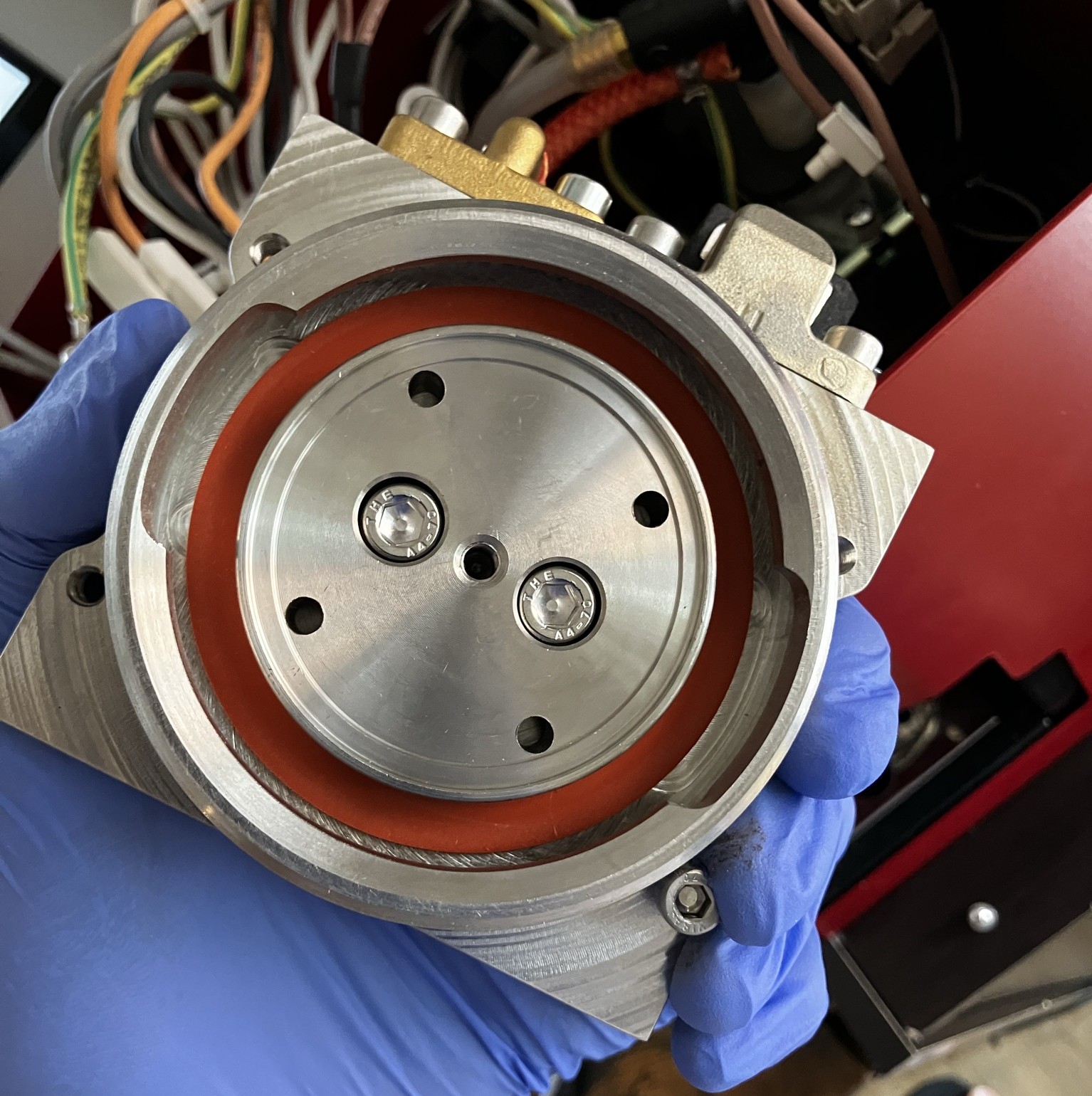
|
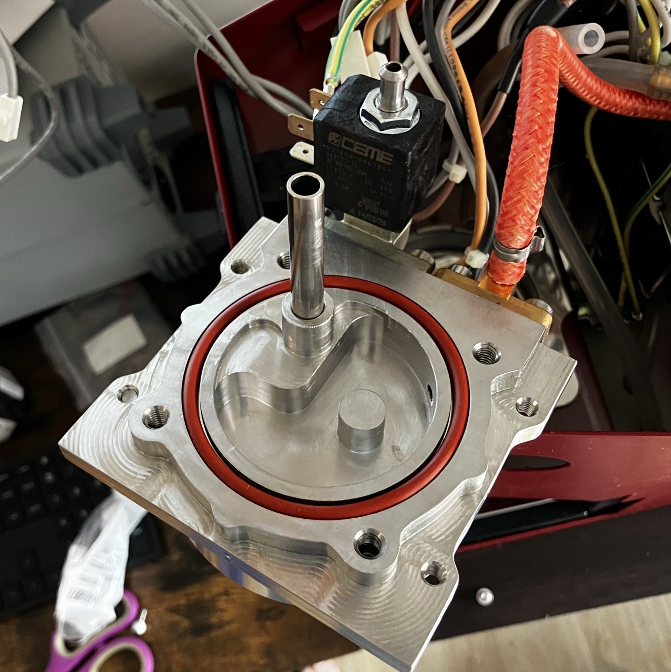
|
The boiler is fitted with four 375 watt cartridge heaters which are installed with high-temperature thermal paste. I attached the steam valve to the boiler, which gets bolted to the top of the group head. The whole assembly is bolted down into the case.
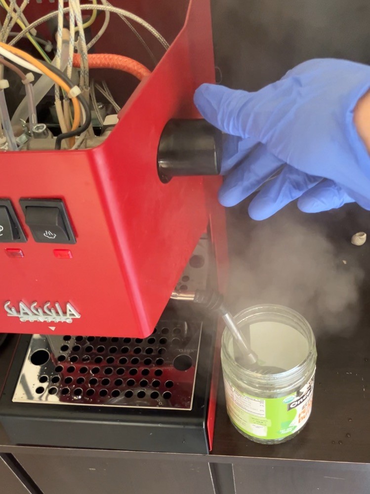
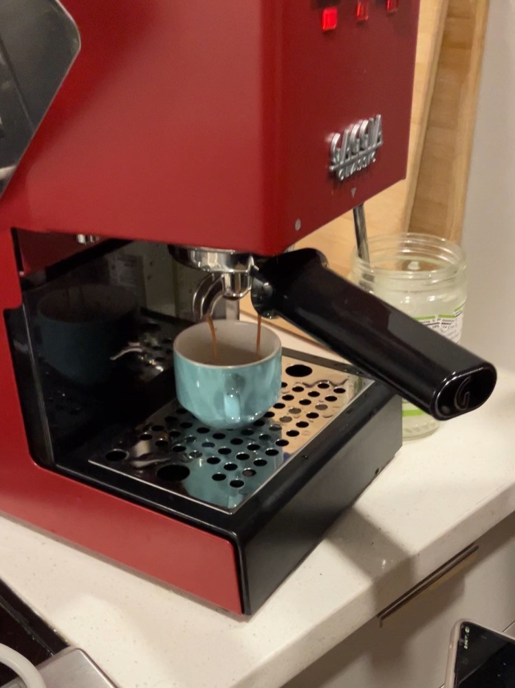
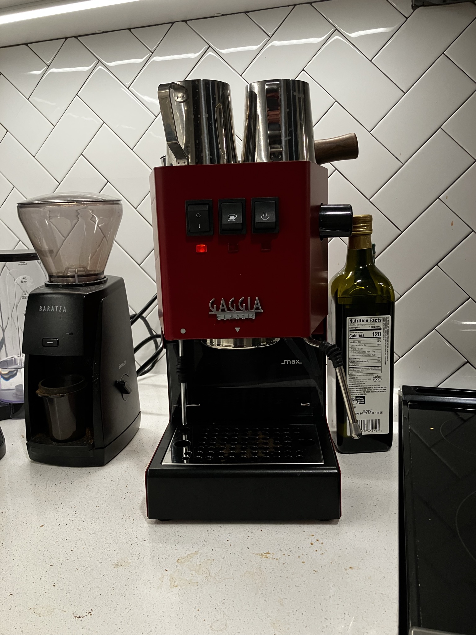
I took the machine outside for testing in case anything caught fire, and since I expected the heaters would smell a little the first time I ran them. Once I had everything working, it all came back inside, and after a few flushing cycles, it was ready to go again.
|
|
|
|